MAIN PUBLICATION :
| Home � TECHNOLOGY � Wind Turbine Technology � Current developments � Alternative drive train configurations |

|
Alternative Drive Train Configurations
Whilst the rotor configuration of large wind turbines as three composite blades in upwind attitude with full span pitch control has consolidated in the past 10 years, there is increasing variety in current drive train arrangements. A few of the considerable variety of layout and bearing options of the drive train, with gearbox and conventional high speed generator, were discussed in Architecture of a Modern Wind Turbine. Other drive train options can be classified as direct drive (gearless) or as hybrid, in other words with some level of gearing (usually one or two stages) and one or more multi-pole generators.
DIRECT DRIVE
The motivation for direct drive is to simplify the nacelle systems, increase reliability, increase efficiency and avoid gearbox issues. A general trend towards direct drive systems has been evident for some years, although there are considerable challenges in producing technology that is lighter or more cost-effective than the conventional geared drive trains. Although these developments continue, direct drive turbines have not, as yet, had a sizeable market share. The exception is Enercon, which has long supplied direct drive generators employing a synchronous generator and having an electrical rotor with windings rather than permanent magnets. Most other direct drive designs are based on PMG technology, using high-strength Neodymium magnets. In July 2008, Siemens installed the first of two new 3.6 MW direct drive turbines to assess whether direct drive technology is competitive with geared machines for large turbines. The two turbines, which have rotor diameters of 107m, use a synchronous generator and permanent magnets.
Figure 3.30: MTorres Wind Turbine Design
Source: MTorres
MTorres wind industry activities started in 1999, leading to development of the TWT-1500, a 1500 kW wind turbine with a multi-pole synchronous generator. The nacelle layout of the MTorres wind turbine is indicated in the schematic diagram above (Figure 3.30).
The Netherlands manufacturer Lagerwey supplied small wind turbines for a number of years and, at a later stage, developed wind turbines of 52, 58 and 72 m diameter with direct drive generators. The LW 52 and LW 58 were wound rotor synchronous machines like Enercon's. Largerwey then sought to develop a larger 1.5 MW direct drive turbine with Zephyros, the Zephyros LW 72. The first installation, at a site in the Netherlands, used a permanent magnet generator design and generation at medium voltage (3 to 4 kV). Subsequently, Zephyros separated from Lagerwey and was acquired by Harakosan. Xiangtan Electric Manufacturing Co Ltd (XEMC) with Harakosan has established XEMC Windpower. Moreover XEMC has also acquired Darwind and plans to install two 5 MW direct drive prototypes in 2010. Thus all the direct drive technology for turbines up to 5MW developed in the Netherlands around the Lagerwey/Zephyros design concepts is now owned by XEMC.
Another notable development in direct drive has come from the Vensys designs, which derive from the Genesys 600 kW prototype of 1997, developed at Saarbrucken University. Vensys turbines may see increasing market presence through the interests of the Chinese developer Goldwind.
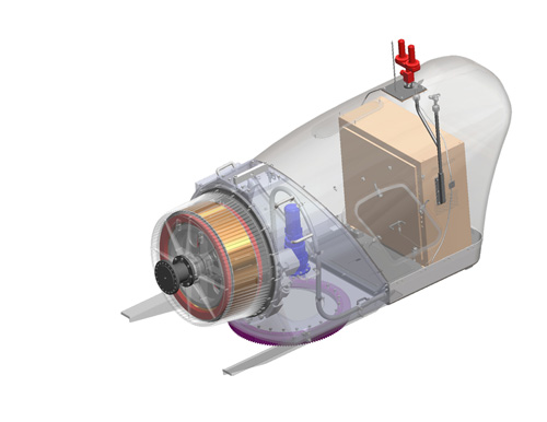
Figure 3.31: Northern Power System 100 kW Drive Train Concept
Source: Northern Power Systems
Northern Power Systems (NPS) developed the Northwind 100 wind turbine. Several hundred 100 kW turbines have been installed, often in remote locations. Their direct drive generator originally employed a salient pole wound rotor technology, but, in line with most new direct drive designs, they have since developed a permanent magnet generator design and an innovative power converter design (Figure 3.31).
HYBRID SYSTEMS
Hybrid systems are a middle route between the conventional solution with three stages of gearing at megawatt scale, and direct drive solutions, which generally demand rather a large diameter generator. The intention is to have a simpler and more reliable gearbox, with a generator of comparable size, leading to a dimensionally balanced and compact drive train.
This design route was launched in the Multibrid concept licensed by Aerodyn. The inventor, George Bohmeke, has pursued that technology with the Finnish company WinWind.
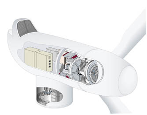
Figure 3.32: WinWind 3 MW
Source: WinWind
A characteristic of the system is the more balanced geometry of gearbox and generator, leading to a compact arrangement. The nacelle need not extend much aft of tower centreline (Figure 3.32), as is generally appropriate for offshore machines, unless it will be accommodating electrical power equipment, such as the converter and transformer.
The structural economy achieved with such an integrated design is well illustrated in Figure 3.32, with the main nacelle structure tending towards an open shell structure, a broadly logical result since, rather like the hub, it also connects circular interfaces (yaw bearing and main rotor bearing) that have substantial angular spacing.
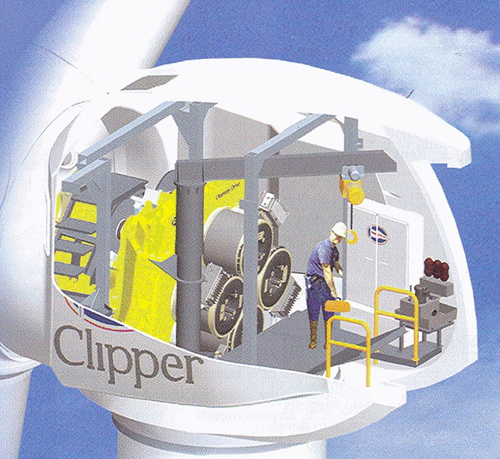
Figure 3.33: Clipper Wind Liberty Wind Turbine with Multi-PMG System
Source: Clipper
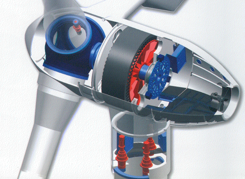
Clipper Wind (Figure 3.33) manufactures 2.5 MW wind turbines, with a hybrid drive train of very distinctive design. After initial research into systems with multiple induction generators, Clipper developed a system with an innovative gearbox with outputs to four PMGs. As with other hybrids, this again leads to a very compact drive train. A subsidiary of Clipper Windpower Plc, Clipper Windpower Marine Ltd, has obtained £4.4 million DECC (UK Department for Energy and Climate Change) funding for development of blades in the “Britannia Project”, a 10 MW offshore wind turbine claimed to be scheduled for deployment in 2011.
Figure 3.34: 5 MW Multibrid Wind Turbine
Source: Multibrid
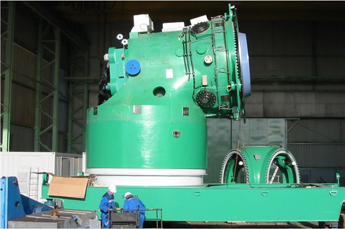
Prokon Nord Energiesysteme GmbH, based in Leer, acquired the previous Multibrid company in 2003. The prototype M5000 (Figure 3.34) was installed in Bremerhaven, and commissioned in 2005. The Multibrid technology was subsequently acquired by Areva in June 2008.
Distinctive features of the M5000 include a highly compact integrated slow rotating drive system, comprising a single main bearing (no main shaft), a single-stage gearbox and a medium speed PMG (58 –147rpm). With a tower head mass of 310 tonnes, the M5000 is apparently the lightest wind turbine rated around 5 MW. Turbine installation is recently completed (November 2009) in the Alpha Ventus offshore project comprising 6 Areva Multibrid M5000 and 6 Repower 5M wind turbines.
OTHER DRIVE TRAIN DEVELOPMENTS
Hydraulic components have figured in drive train design for some time in motors, brakes, fluid couplings or torque limiting systems. Hydraulic drives comprising pump(s) and motor(s) for main power transmission were employed in the unsuccessful Bendix 3 MW prototype of the early 1980s, but this design route was not pursued. Key problems were inadequate capacity, efficiency, reliability and life of existing commercial hydraulic components – the lack of components specifically designed for the needs of efficient wind power generation.
The Scottish company, Artemis has addressed this and has developed a high efficiency, long life, ring cam pump, with electronically controlled poppet valves to suit wind turbine applications. Ring cam pumps are very rugged and reliable. Those, for example, made by the Scottish supplier, MacTaggart Scott are welded into the hulls of submarines for life. Development work, which will subsequently consider wind power transmission systems in the 5 to 10 MW range, is progressing with funding assistance from the UK Carbon Trust. Artemis claims a 20 mass reduction in nacelle systems can result, commenting that the power density of hydraulic machines is at least three times higher than the most advanced electric motor.
Another recent use of fluidic systems is in the Voith transmission system, adopted by De Wind (now owned by Composites Technology Inc.). This is essentially a way of realising a variable speed in the gearbox, thereby allowing direct connection of a synchronous generator to the output and hence avoiding the need for an electrical power converter.
The Voith WinDrive system uses a hydrodynamic torque converter to provide the variable speed relationship between the output shafts. WinDrive is essentially a mechanical solution to variable speed operation, based on a torque converter in combination with a planetary gear system. As a fluid machine, the torque converter is well matched to the wind turbine rotor and, via the fluid in the converter, the system decouples the input and output shafts absorbing input torque spikes and providing damping of vibrations.
With WinDrive, added mechanical complexity and cost in the gear system is compensated by elimination of the cost, mass and losses of an electrical power converter. The damping and compliance, intrinsic in the hydrodynamic coupling, ensures that a synchronous generator can be used. The Voith technology is long established in industrial drives, but the wind power application presents new challenges, especially in fatigue life and efficiency, which Voith have been addressing.
| << Rotor blade development | Controller capabilities >> |
| Acknowledgements | Sitemap | Partners | Disclaimer | Contact | ||
|
coordinated by  |
supported by  |
The sole responsibility for the content of this webpage lies with the authors. It does not necessarily reflect the opinion of the European Communities. The European Commission is not responsible for any use that maybe made of the information contained therein. |
