MAIN PUBLICATION :
| Home � TECHNOLOGY � Wind resource estimation � Local wind resource assessment and energy analysis � The prediction of the energy production of a wind farm � The prediction of the energy production of a wind farm |

|
The Prediction of the Energy Production of a Wind Farm
In order to predict the energy production of the wind farm it is necessary to undertake the following tasks:
- Predict the variation in the long-term wind speed over the site at the hub height of the machines, based on the long-term wind speeds at the mast locations;
- Predict the wake losses that arise as a result of one turbine operating behind another – in other words in its wake; and
- Calculate or estimate the other losses.
Information Required for an Analysis
In addition to the wind data described in the earlier sections, inputs to this process are typically the following:
- Wind farm layout and hub height;
- Wind turbine characteristics, including power curve (the curve which plots the power output of a turbine as a function of the wind speed) and thrust curve (the equivalent curve of the force applied by the wind at the top of the tower as a function of wind speed);
- Predicted long-term site air density and turbulence intensity (the turbulence intensity is the ‘gustiness’ of the wind);
- Definition of the topography over the site and surrounding area; and
- Definition of the surface ground cover over the site and surrounding area.
Energy Production Prediction Methodologies
Typically, the prediction of the variation in wind speed with height, the variation in wind speed over the site area and the wake interaction between wind turbines are calculated within a bespoke suite of computer programmes, which are specifically designed to facilitate accurate predictions of wind farm energy production. The use of such tools allows the energy production of different options of layout, turbine type and hub height to be established rapidly once models are set up. Such programmes are commonly described as 'wind farm design tools' (WFDT).
Within the WFDT, site wind flow calculations are commonly undertaken, using the WAsP model, which has been widely used within the industry over the past decade. There are also other commercial models, physically similar to WAsP, that are sometimes used. This area of the wind farm energy calculation is in need of the greatest level of fundamental research and development. Flow models that can be used in commercial wind farm development have to be quick to execute and have to be reliable and consistent. At present, the industry generally opts for simple but effective tools such as WAsP. However, in the last few years, use of computational fluid dynamics (CFD) codes is increasing, although CFD tools are typically used in addition to, and not instead of, the more simple tools to investigate specific flow phenomena at more complex sites. CFD tools need to be used with care, as the results are sensitive to modelling assumptions. CFD codes are also substantially more computationally onerous to run. Typical use of CFD tools is first, to give another estimate of the speed-up at the site, and second, to identify hot spots, in other words areas where the wind conditions are particularly difficult for the wind turbines. In particular, such tools are starting to be used to assist the micrositing of wind turbines on more complex terrain sites.
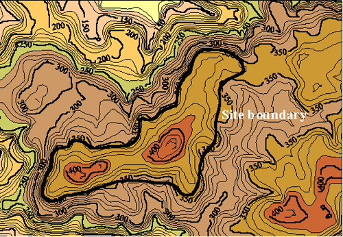
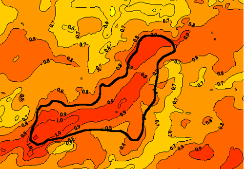
Thus, the challenge is to take a topographical map and the long-term wind rose at a known point on the map, and use this information to calculate the long-term wind speed at all the points on the map where the intention is to place wind turbines. A typical set of topographical input and wind contour output (normalised to the wind speed at the location of an on-site mast) is shown in Figure I.2.10 for a hilly area approximately 6 km by 4 km in size.
Figure I.2.10: Input Topography (Top) and Output Normalised Wind Speed (Bottom)
Source: Garrad Hassan
The WAsP model does have shortcomings under certain topographical and flow conditions, as the model is designed for specific wind flow conditions, and so for slopes steeper than approximately 20° where the flow will separate, the model is beyond its formal bounds of validity. It therefore needs to be used with care and experience and not as a ‘black box’. As indicated above, it does not include ‘viscous effects,’ which cause the wind to ‘separate’ as it flows over a sharp change in topography. The WAsP model will follow the terrain, whereas the real wind will behave as shown in Figure I.2.11. Therefore, in complex terrain, the manual interpretation of calculation results is required.
Figure I.2.11 An Example of Flow Separation Over a Hill
Source: Garrad Hassan
There is an enormous amount of work in progress in all aspects of engineering, quite distinct from the wind energy industry, in which developments are being made in the numerical prediction of complicated flows. Most notably, these efforts centre on aerospace problems – accurate flow over aircraft wings and fuselage, for example, or internal flows in turbo-machinery. Efforts are now being made to apply such models to the arbitrary terrain that defines a wind farm (complex topographies characterising wind farms). There is still a long way to go before these models can be considered sufficiently reliable, however, to replace rather than complement conventional tools.
The energy estimate is only as good as its weakest link and hence its accuracy is largely defined by this step – the topographical wind model. Data sets now exist that can be used for the validation of new codes, and developments are expected. The task is, nevertheless, a demanding one, and accurate calculation of the flow over steep terrain is challenging. At present, it is necessary to use a mixture of computation and human insight. For such sites, there is currently no alternative to a comprehensive monitoring campaign to provide data that may be used to initiate localised flow modelling.
Once the topographical effects on the flow have been computed, it is necessary to determine how the individual turbines affect one another - the wake effects. If a turbine is working downstream of another (in its wake), then it will see less wind than it would if it were in the free stream. For some types of wind rose and wind farm design this effect can be significant, of the order of 15 per cent in lost energy, and hence needs to be carefully calculated. The models that estimate this loss are known as ‘wake models.’ Different complexities of wake model are used in the various commercially available WFDTs. These tools are now well validated for a variety of different types of wind farm layout. However, it is well known that they do not work well for very tightly packed wind farms, such as those described above at Palm Springs, and further fundamental work is required to improve the modelling in this area. Also, with the advent of data from large offshore wind farms, it is apparent that some adjustments are required to conventional wake models for very large wind farms.
It is important to appreciate that, as the distance of the turbine from the meteorological mast increases, the uncertainty in the prediction also increases. This increase in uncertainty is typically more rapid in complex terrain than in simple terrain. Experience of the decrease in accuracy with distance from the mast, when using models such as WAsP, is inherent in making recommendations regarding the appropriate number of meteorological masts for a wind farm site, as discussed above. The WFDT’s also allow environmental constraints to be included – areas of the site, which may not be used because of rare flora or fauna, noise constraints, visual intrusion, shadow flicker or land ownership, for example. These considerations are discussed in more detail below.
The ability of the WFDTs to provide an integrated model of a wind farm also allows them to be used to optimise the wind farm design. This task is performed in an automatic process. It moves the turbines to provide the best possible compromise between concentration of the wind turbines at the maximum wind speed areas of the site, which maximises wake losses (loss of energy by turbulence effects of a wind turbine on its neighbours), and the spreading out of the turbines all over the site to minimise wake loss. This process can be undertaken successfully at the same time as observing the environmental and ownership constraints. The development of these tools has been a significant development in wind farm design. The successful completion of an energy calculation using a WFDT may be considered as Milestone 2 of Figure I.2.2.

| Information required for an analysis >> |
| Acknowledgements | Sitemap | Partners | Disclaimer | Contact | ||
|
coordinated by |
supported by  |
The sole responsibility for the content of this webpage lies with the authors. It does not necessarily reflect the opinion of the European Communities. The European Commission is not responsible for any use that maybe made of the information contained therein. |
