MAIN PUBLICATION :
| Home � TECHNOLOGY � Wind Turbine Technology � The Technical Challenge of a Unique Technology � Architecture of a modern wind turbine |

|
Architecture of a Modern Wind Turbine
Many developments and improvements have taken place since the commercialisation of wind technology in the early 1980s, but the basic architecture of the mainstream design has changed very little. Most wind turbines have upwind rotors and are actively yawed to preserve alignment with the wind direction.
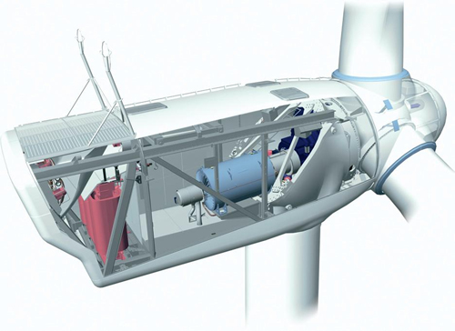
Figure 3.6: Typical Nacelle Layout of a Modern Wind Turbine
Source: Nordex
The three-bladed rotor proliferates and typically has a separate front bearing, with low speed shaft connected to a gearbox that provides an output speed suitable for the most popular four-pole (or two -pole) generators. This general architecture is evident in Figure 3.6. Commonly, with the largest wind turbines, the blade pitch will be varied continuously under active control to regulate power in higher operational wind speeds.
Support structures are most commonly tubular steel towers tapering in some way, both in metal wall thickness and in diameter from tower base to tower top. Concrete towers, concrete bases with steel upper sections and lattice towers, are also used but are much less prevalent. Tower height is rather site specific and turbines are commonly available with three or more tower height options.
Figure 3.7: Ecotecnia 100 Nacelle Layout
Source: Ecotècnia
The drive train of Figure 3.6 shows the rotor attached to a main shaft driving the generator through the gearbox. Within this essentially conventional architecture of multi-stage gearbox and high speed generator, there are many significant variations in structural support, in rotor bearing systems and in general layout. For example, a distinctive layout (Figure 3.7) has been developed by Ecotècnia (Alstom), which separates the functions of rotor support and torque transmission to the gearbox and generator. This offers a comfortable environment for the gearbox, resulting in predictable loading and damping of transients, due to its intrinsic flexibility. Among the more innovative of a large variety of bearing arrangements is the large single front bearing arrangement adopted by Vestas in the V90 3 MW design (Figure 3.8). This contributes to a very compact and lightweight nacelle system.
Figure 3.8: Vestas V90 Nacelle Layout
Source: Vestas
Whilst rotor technology is set amongst the leading commercial designs and the upwind three-bladed rotor prevails generally, more unconventional trends in nacelle architecture are appearing. The direct drive systems of Enercon are long established, and many direct drive designs based on permanent magnet generator (PMG) technology have appeared in recent years. A number of hybrid systems, such as Multibrid, which employ one or two gearing stages, and multi-pole generators have also appeared. These developments are discussed in Technology Trends. It is far from clear which of the configurations is the optimum. The effort to minimise capital costs and maximise reliability continues – the ultimate goal is to minimise the cost of electricity generated from the wind.
| << Design drivers for modern technology | Growth of wind turbine size >> |
| Acknowledgements | Sitemap | Partners | Disclaimer | Contact | ||
|
coordinated by  |
supported by  |
The sole responsibility for the content of this webpage lies with the authors. It does not necessarily reflect the opinion of the European Communities. The European Commission is not responsible for any use that maybe made of the information contained therein. |


